Active Member
|
[China]

Address: No.18,Changjiang South Road, Tianyuan District, Zhuzhou City, Hunan Province,China
Contact name:Joy Zhu

Zhuzhou XinHua Cemented Carbide Co., Ltd. |
|
|
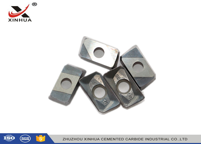
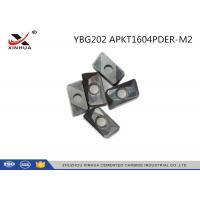
Indexable Carbide Insert Milling Inserts For Metal Cutting YBG202 APKT1604
Describtion:
| Insert Application Guide | ||
| Finishing | Universal | Roughing |
| Hard and Wear resistant | Wear Resistant and Tough | Tough and Impact Resistant |
| PVD and CVD Coating | PVD and CVD Coating | PVD and CVD Coating |
| Small Nose radius | Medium Nose Radius | Large Nose Radius |
| Light Honed Edge | Medium Honed Cutting Edge | Heavy Honed Cutting Edge |
| Small Chipbreaker | Medium Chipbreaker | Large Chip Breaker |
| Cutting Date | ||
| Finishing | Universal | Roughing |
| Small Depth of cut (ap) | Medium Depth of cut (ap) | Large Depth of cut (ap) |
| Small Feed per Revolution (f n) | Medium Feed per Revolution (f n) | High Feed per Revolution (f n) |
| High Surface Cutting Speed (Vc) | Medium Surface Cutting Speed (Vc) | Low Surface Cutting Speed (Vc) |
| Use Coolant if Insert Allows | Use Coolant if Insert Allows | Use Coolant if Insert Allows |
Application:
For Roughing, use a tough coated insert grade with a large nose radius, heavy honed cutting edge and large chipbreaker. Cut at a low SFM with a large Depth of Cut (ap) and high Feed Rate per Rev. (fn)
For Universal, use a hard, tough & wear resistant coated insert grade with a medium nose radius, honed cutting edge and medium chipbreaker. Cut at a medium SFM with a medium Depth of Cut (ap) and medium Feed Rate per Rev. (fn)
For Finishing, use a hard & wear resistant coated insert grade with a small nose radius, sharp to light honed cutting edge and small chipbreaker. Cut at a high SFM with a medium Depth of Cut (ap) and medium Feed Rate per Rev. (fn)
Optimum: Insert Wear, decrease Spindle Speed (n) and/or increase Feed (fn) or change to a harder insert grade. Insert Chipping, increase Spindle Speed (n), decrease Feed (fn), and/or change to a heavier honed edge or change to a tougher insert grade.
Coolant: Use Coolant, if the insert grade allows, and always use high pressure coolant to remove the hot chips and heat from the insert to reduce thermal shock
1. Substrate - The alloy carbide's properties, grain size, and cobalt content.
2. Geometry - The physical characteristics of an insert that differentiates one shape from the next.
3. Tolerances - The allowed deviation of all insert dimensions.
4. Relief Angle - The angle measured from the vertical line perpendicular to the cutting edge of the insert and the cutting face of the insert.
5. Rake Angle - The angle formed on the insert from the top surface area and the bottom of the insert chip flow area when parallel to the floor. 6. Chipbreaker - The formed groove or recess along the cutting edge of the insert that breaks chips into small manageable lengths.
7. Edge Preperation - The process used to prepare the insert's edge cutting condition for specific application and material. Achieved by honing, chamfering, "T" land or any combination there of.
8. Coating - Thin layer of titanium nitrade on the surface of the insert that allows for greater cutting speeds, wear resistance and longer insert life.
9. Grade - A combination of substrate and coating that determines the hardness and toughness of the insert.
| Material | Material Characteristics |
| Carbon Steel, Alloy Steel and Tool Steel 36-48 HRC: | • Higher carbon content • Higher chrome, nickel, and moly content • Tough material to machine • Abrasive • Difficult to break and control the chip flow • The material surface will harden when machined at high speed • Good surface finish |
| Ferritic, Martensitic, and PH Stainless Steel under 48 HRC | • Brittle • Stringy chips • High cutting force • The material will harden when machined at high speed. |
| Austenitic Stainless Steel: | • Becomes gummy under machining operations due to nickel content • Very difficult to machine in soft conditions • Very difficult to machine at a small depth of cut • Develops a tough string of chips that are difficult to control. Forms a build-up on the insert tip • Low thermal conductivity results in excess heat at the insert tip • Material surface will harden due to high chromium content |
| Ductile and Malleable Cast Iron | • Very difficult to machine • Small depth of cut • Spherical form graphite makes machining difficult • The carbide concentration creates hard spots • The material structure is not uniform • The crater wear and flank of the insert makes machining difficult • The insert tool life is less than gray cast iron |
| Gray Cast Iron | • Flake form of graphite makes machining easy • Contains scale, inclusions and sand in the surface • The material will break easily on the end of the cut • Tendency to chatter and vibrate on thin wall section • Chucking and rigidity of the workpiece is extremely important to minimize distortion, to achieve a good finish and close tolerance |
Specification: