
|
|
[China]

Trade Verify
Address: Address: N0.1, Dongli Road, Donglai, Zhangjiagang City, Jiangsu Province, China
Contact name:Sandy Chen

Zhangjiagang HuaDong Boiler Co., Ltd. |
|
Verified Suppliers
|
|
|
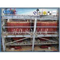
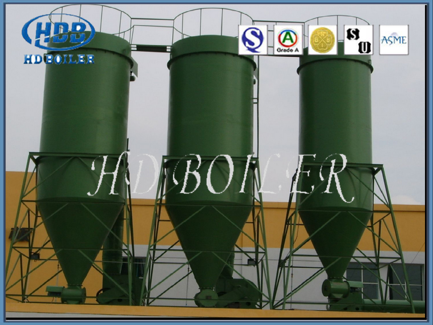
Boiler Steel Multi Conical Cyclone Separator for CFB Coal-fired Boilers of Thermal Power Plant
Product Description
Cyclone separator is a kind of equipment used for separating gas-solid system or liquid-solid system. The working principle is that the solid particles or droplets with large inertia centrifugal force are separated from the outer wall by the rotating motion caused by the tangential introduction of air flow. The main characteristics of cyclone separator are simple structure, high operating flexibility, high efficiency, convenient management and maintenance, low cost. It is used for collecting dust with diameter of 5-10 μm. It is widely used in pharmaceutical industry. It is especially suitable for dust particles which are thicker and contain more dust. Under high temperature and high pressure conditions, it is also often used as an internal separation device in fluidized bed reactor or as a pre-separator. It is a widely used separation equipment in industry.
Application
1. Gas / Fume filtration for industrial boiler .
2. Metallurgy Furnace fumes filtration
3. Woodworking plant
4. Machine processing plant
5. Powder processing plant
6. cement production process
Principle and Working
Cyclone separator is a dry gas-solid separator which separates dust from airflow by centrifugal force produced by gas-solid mixture in high-speed rotation. Because the centrifugal force acting on the particles is far greater than the gravity and inertia force, the separation efficiency is higher.
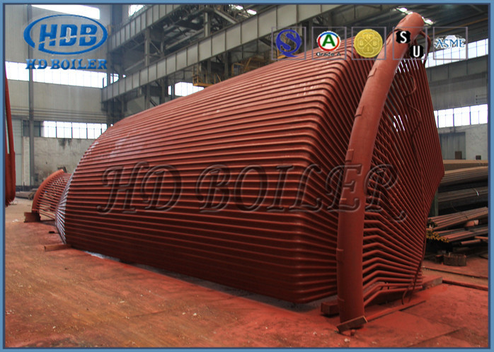
The separation principle and structure of the commonly used tangential inlet cyclone separator are shown in the figure. The main structure is a conical cylinder with a gas inlet pipe in the tangential direction of the upper section of the cylinder, a exhaust pipe inserted into a certain depth in the cylinder on the top of the cylinder, and a powder outlet receiving fine powder at the bottom of the conical cylinder. When the dust-laden airflow enters the cyclone separator at the speed of 12-30m/s from the intake pipe, the airflow will change from linear motion to circular motion. Most of the rotating airflow flows downward from the cylinder to the cone along the wall. In addition, under the action of centrifugal force, the particles are thrown to the wall of the separator. Once the dust particles contact the wall, they lose inertia force. The momentum of downward axial velocity near the wall falls along the wall and enters the ash discharge pipe, and falls into the collection bag from the outlet. In the process of downward rotation, the outer swirling flow continuously flows into the central part of the separator, forming a centripetal radial flow, which constitutes the inner swirling flow of upward rotation. The rotation direction of inner and outer swirling flow is the same. Finally, the purified gas passes through the exhaust pipe and is discharged, and a part of the finer dust particles that have not been separated also escape. The other small part of the gas flowing from the intake pipe flows downward along the outer side of the exhaust pipe through the top cover of the cyclone separator. When it reaches the lower end of the exhaust pipe, it converges with the upward internal swirling flow and enters the exhaust pipe. The fine particles dispersed in the upper swirling flow in this part are also takes away, and then trapped by a bag filter or a wet dust collector.
The purified natural gas enters the cyclone separation zone through the inlet of the equipment.When the impurity gas enters the cyclone separation pipe along the axis, the airflow is strongly rotated by the guide vane, and the airflow enters the cyclone cylinder spirally downward along the cylinder. The high density droplets and dust particles are thrown toward the wall of the cyclone under the action of centrifugal force. Under the action of gravity, they fall down along the wall of the cylinder and flow out of the cyclone pipe dust outlet to the liquid storage area at the bottom of the equipment, and finally flow out from the liquid outlet of the equipment bottom. The rotating airflow in the cylinder shrinks and flows to the center, forming a secondary eddy current upward, which flows through the air duct to the gas purification chamber, and then flows out through the top outlet of the equipment.
Operation
Cyclone separators operate by incorporating centrifugal, gravitational, and inertial forces to remove fine particles suspended in air or gas. These types of separators use cyclonic action to separate particulates from a gas stream. Typically, PM enters the cyclone separator at an angle (perpendicular to the flow stream, tangentially, or from the side), and is then spun rapidly. A centrifugal force is created by the circular airflow that throws the particulate towards the wall of the cyclone. Once the PM hits the wall, it falls into a hopper below. “Clean” exhaust is then either blown through or recirculated to be filtered again.
Technical Data
| Model | Air volume(m3/h) | Total height mm) | |||
| Inlet velocity(m/s) | |||||
| 15 | >18 | 20 | 22 | ||
| CLT/A-2.5 | 580 | 690 | 770 | 850 | 1100 |
| CLT/A-3.0 | 830 | 1000 | 1100 | 1220 | 1380 |
| CLT/A-3.5 | 1140 | 1360 | 1510 | 1670 | 1600 |
| CLT/A-4.0 | 1480 | 1780 | 1960 | 2170 | 1800 |
| CLT/A-4.5 | 1870 | 2250 | 2480 | 2700 | 2050 |
| CLT/A-5.0 | 2320 | 2780 | 3080 | 3400 | 2300 |
| CLT/A-5.5 | 2800 | 3360 | 3720 | 4100 | 2500 |
| CLT/A-6.0 | 3340 | 4000 | 4440 | 4900 | 2700 |
| CLT/A-6.5 | 3920 | 4700 | 5210 | 5700 | 2900 |
| CLT/A-7.0 | 4540 | 5440 | 6030 | 6670 | 3200 |
| CLT/A-7.5 | 5210 | 6250 | 6920 | 7650 | 3400 |
| CLT/A-8.0 | 5940 | 7130 | 7900 | 8730 | 3600 |
| CLT/A-9.0 | 7510 | 9000 | 9980 | 11000 | 4100 |
| CLT/A-10.0 | 9280 | 11100 | 12300 | 13600 | 4600 |
| CLT/A-10.6 | 10400 | 12400 | 13800 | 15200 | 4800 |
| CLT/A-11 | 11200 | 13400 | 14800 | 16400 | 5000 |
| CLT/A-12 | 13300 | 15900 | 17600 | 19500 | 5400 |
| CLT/A-13 | 15600 | 18700 | 20700 | 23370 | 5900 |
| CLT/A-14 | 18100 | 21700 | 24000 | 26600 | 6400 |
| CLT/A-15 | 20800 | 24800 | 27600 | 30500 | 6900 |
| CLT/A-16 | 23700 | 28400 | 31500 | 34800 | 7360 |
| CLT/A-17 | 26800 | 32100 | 35600 | 39300 | 7860 |
| CLT/A-18 | 30000 | 36000 | 39900 | 44100 | 8300 |
| CLT/A-19 | 33500 | 40200 | 44500 | 49200 | 8790 |
| CLT/A-20 | 37100 | 44500 | 49300 | 54500 | 9200 |

Advantages
1. Low capital cost.
2. Ability to operate at high temperatures.
3. Can handle liquid mists or dry materials.
4. Low maintenance requirements (no moving parts).
5. Small footprint - requires relatively small space.
Quality Control
1. Fabrication area of 200,000 square meters
2. 150 Engineers
3. 600 Coded welders
4. 60 Licensed Inspectors(NDT Level-III instructors)
5. Class-A Licenses for Design and Manufacture Boiler
6. ISO 9001:2008 Quality System
7. ASME Certificate of Power Boilers
8. ASME 'S','U' and NB stamp authorization


