

Active Member
|
[China]

Address: NO.27,Jinlanling Street,Taigongling Village Dongguan 523829,Guangdong,China
Contact name:Eric

Aolittel Technology Co.,Ltd |
|
|
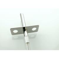
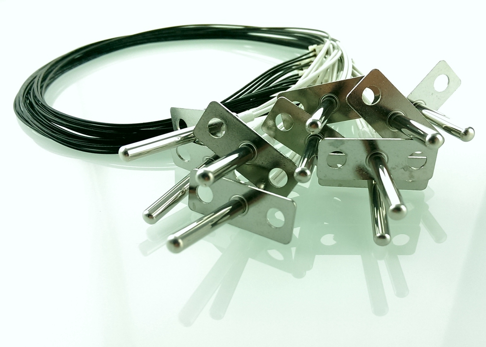
High Temperature KitchenAid Frigidaire Range Oven Probe Micro Temperature Sensor 100K 3950 With 4x50mm Stainless Steel
Description
The temperature probe lets you cook roasts and poultry to the exact internal temperature you want, taking the guess work out of determining whether a piece of meat is done or not. You can use the temperature probe with the oven set to Bake, Convection Bake, or Convection Roast. When you use the temperature probe, the internal temperature is shown on the display when it reaches 100°F.
___________________________________________________________ Download________
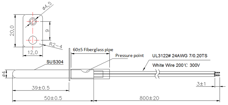
Dimension (mm)
| NO | COMPONENT | MATERIAL AND SPECIFICATIONS | Q'TY | REMARK |
| 1. | Housing | ø4×50+12×20 Stainless steel | 1 | |
| 2. | Element | R25=100KΩ±1% B25/50=3950K±1% DD | 1 | |
| 3. | Wire | UL3122# 24AWG 200℃ 300V L=800mm | 2 | White |
| 4. | Casing | ø4 60±5 Fiberglass pipe | 1 | White |
| 5. | Terminal | Peeling tin plating |
| NO | Item | Sign | Test Conditions | Min. | Normal value | Max. | Unit |
| 1. | Resistance at 25℃ | R25 | Ta=200±0.05℃ PT≦0.1mw | 9.9 | 10 | 10.1 | KΩ |
| 2. | B Value | B25/50 |  | 3910.5 | 3950 | 3989.5 | k |
| 3. | Dissipation factor | σ | Ta=25±0.5℃ | 2.5 | / | mw/℃ | |
| 4. | Time constant | τ | Ta=25±0.5℃ | / | / | 20 | sec |
| 5. | Insulation resistance | / | 500VDC | 100 | / | / | MΩ |
| 6. | Withstand voltage | / | 1500V AC (3mA) | 5 | / | / | Sec |
| 7. | Operating temp.range | / | / | -10 | / | +200(head) | ℃ |
 |
 |
 |
 |
 |
| NO | Item | Technical requirements | Test conditions and method |
| 1. | High temp. Test | DR/R25£±3%
DB/B£±3%
No change with withstand voltage, Insalution performance. Appearance without damage. | 200±5℃,power on 500±24 hrs,DC0.2mA |
| 2. | Low temp. tes | -10±5℃,power on 500±24 hrs,DC0.2mA | |
| 3. | Endure moisture test | Store in environment 55±2℃,90%-95%RH for 240±24 hrs | |
| 4. | Temp. cycle test | –20℃×30min→Room temp.×10min→ in 100℃ water×30min→Room temp.×10min 10 cycles | |
| 5 | Load electrify test | Power on DC1mA, 500hrs in room temp. and humid. | |
| 6 | Tensile tests | Applying 2 kg force lasts 1 min. | |
| 7 | Drop test | Free fall into concrete floor from height 1M ,10 cycle. | |
| 8 | Vibration test | Frequency range:10~55HZ Total amplitude 1.52mm 1 cycle 1 min ,direction and time X,Y,Z axs 2Hr each. | |
| 9 | Bending test | Bend 180°binding site wire and epoxy resin.Back and forth 10 times |
How do I check an oven temperature sensor?
A failed oven sensor is most often responsible for an F3 or F4 error messages on electronically controlled ovens. It can also be responsible for an F1, F2, F5, F10, F30, F31, F3-E0, F3-E1, F3-E2, F3-E3, E0-F3, E1-F3, E2-F3 and E3-F3 error message as well as just an erroneous temperature display on the control.

While the sensor probe itself is most often the cause of an F3 or F4 fault code, it is not a certainty. A problem in the wiring harness between the control and the sensor or the electronic control itself could each result in the same error codes being displayed. It will be necessary to isolate which is the actual cause of the fault condition in order to correct it.

Most oven sensors have a mounting plate that is attached to the rear wall of the oven cavity interior. That mounting plate is usually held in place by 2 screws which go through it into the rear oven liner to hold it in place.

Testing the Oven Sensor
Testing of the sensor has to be performed while the problem is occurring. If the problem is present as soon as an oven function is selected and even before heating has begun, the sensor itself can be tested to see if it is within specs. The most common oven sensor currently used should measure approximately 1080 ohms when at room temperature. See below for a detailed temperature/resistance chart.
Once power has been disconnected from the appliance (do NOT just rely on the controls being off!), the sensor mounting screws can be removed. The mounting screws can sometimes be rusted or seized in place so make sure a good screwdriver is used so the screw heads don't get stripped in the process.

Once the retaining screws have been removed, the sensor should be able to be pulled (at least slightly) into the oven cavity. There should be a plastic terminal block on the wires which may have to be manipulated to get it through the hole in the rear of the oven cavity. Once through, the connector can be disconnected to access the sensor wire terminals to perform a resistance test of it.
![]() Some range and oven models may have the oven sensor inserted
through the oven liner from the rear. If the sensor mounting screw
heads are not visible from inside the oven cavity, the back panel
of the range or oven may need to be removed to access the sensor
mounting and harness connector to test and replace it. On a built
in oven, that may involved removing the appliance from its
enclosure.
Some range and oven models may have the oven sensor inserted
through the oven liner from the rear. If the sensor mounting screw
heads are not visible from inside the oven cavity, the back panel
of the range or oven may need to be removed to access the sensor
mounting and harness connector to test and replace it. On a built
in oven, that may involved removing the appliance from its
enclosure.

Once the sensor connection is accessible, set an ohm meter on the R x 10 ohm or R x 1K ohm scale and test between the two metal terminals in the sensor's connector block.
Error Message ~ Only While in Use ~
If the error message (or an erroneous temperature display) only occurs during use, it would be dangerous to attempt to remove the sensor for testing while the oven is hot. In this case finding where the sensor circuit wires attach to the electronic control will be necessary to perform testing at that point.
How to access the electronic control's connections will depend on the design of the particular appliance. Often the temperature sensor wires will be violet colored where they connect to the control but check the particular appliance's wiring diagram to be sure.
Install an oven thermometer in the oven and operate the appliance until the problem occurs. The oven should be allowed to cycle on and off on its own at least twice. Disconnect power from the appliance (do NOT just rely on the controls being off!), access the control, isolated sensor wiring and measure the resistance of the sensor circuit. The readings should be close to what is listed in the following chart at the various oven temperatures.
| Common Oven Sensor Approx. Values | |
|---|---|
| Temperature (F/C) | Resistance (ohms) |
| 70°F / 21°C | ~1080 +/-4.9 |
| 100°F / 37.7°C | ~1143 +/-6.0 |
| 250°F / 121°C | ~1453 +/-8.9 |
| 350°F / 176.6°C | ~1654 +/-10.8 |
| 450°F / 232°C | ~1852 +/-13.5 |
| 550°F / 287.7°C | ~2047 +/-15.8 |
| 650°F / 343.3°C | ~2237 +/-18.5 |
| 900°F / 482.2°C | ~2697 +/-24.4 |
| *Does not apply to older GE senser # WB21X158 | |
If your readings vary greatly from the chart above, the sensor may be suspect but its wiring harness is still a possibility. Once the oven has fully cooled measure the sensor circuit resistance again at the control connection. Then disconnect the sensor itself (see above) and directly measure its readings. If these two tests measure the same, it would usually indicate the wiring harness is not the problem leaving the sensor as the most likely culprit.
Note
Some Kenmore range models have a thermal fuse in the wiring harness to the oven sensor. A failure of it could be responsible for an F3 fault code instead of the sensor itself or its wiring harness. Check the range's wiring diagram for that possibility. On models employing that extra safety device, it can sometimes be found inside the control console.
Tip
Often a replacement sensor will not have the same plug-in connector that the original sensor used. In such a case the wires may need to be cut and spliced together using ceramic wire nuts. The use of ceramic or porcelain wire nuts instead of plastic insure that they will not melt with the heat of the oven, especially on self-cleaning models.


