Active Member
|
[China]

Address: NO.27,Jinlanling Street,Taigongling Village Dongguan 523829,Guangdong,China
Contact name:Eric

Aolittel Technology Co.,Ltd |
|
|
TE Connectivity PolySwitch Analogue Radial Leaded PTC Resettable Fuse TRF012 250V 0.12A
Introduction
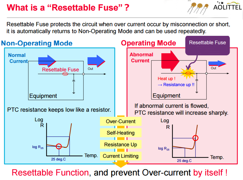
Overcurrent protection is a most basic necessity for electrical devices. However, many people are familiar with fuses and household circuit breakers, but few of them are intimately familiar with the kinds of overcurrent protection devices-Ao littel PTC Resettable Fuse that are found in electronics board. Though not a comprehensive list, there are basically three types of overcurrent protection devices in electronics. In order of increasing sophistication they are:
• One-shot fuses (One-time fuse, normally called SMD Fuse,Glass Fuse,Ceramic Fuse,Subminiature fuse)
• Positive Temperature Coefficient PTC resettable fuses
• Electronic fuses (eFuses)
______________________________________________________________________________ Download________
| PTC Resettable Fuse Family Member | ||
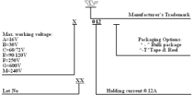
| No. | Voltage | Series |
| 1 | 16V | TRA |
| 2 | 30V | TRB |
| 3 | 60V/72V | TRC |
| 4 | 90V/120V | TRE |
| 5 | 240V/265V | TRM |
| 6 | 250V | TRF |
| 7 | 600V | TRG |
Advantage
• 0.02 – 2A hold current range, 60VDC operating voltage
• 250VAC interrupt rating
• Fast time–to-trip
• Binned and sorted narrow resistance ranges available
• RoHS compliant, LeadFree and Halogen-F
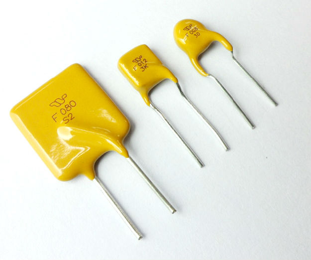
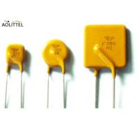
• Radial Leaded Devices
• Cured, flame retardant epoxy polymer insulating material meets UL 94V-0 requirements
• Bulk Package, or tape and reel available on most models
• Agency recognition: UL,CUL,TUV,ROHS,CTI
• Used to help telecom networking equipment meet the protection requirements specified in ITU K.20 and K.21.
• Meet ISO/TS16949: 2009 / IATF16949 / AEC-Q200 Quality management systems
Applications
Almost anywhere there is a low voltage power supply, up to DC60V and a load to be protected, including:
Electrical Characteristics
| P/N | IH, (A) | IT,(A) | Vmax,(v) | Imax,(A) | Vmax,(v) | (A) | (Sec.) | Pd typ(W) | Rmin | Rmin | R1max |
| TRF002 | 0.020 | 0.045 | 60 | 3.0 | 250 | 1.0 | 0.1 | 1.0 | 65 | 145 | 240 |
| TRF004 | 0.040 | 0.080 | 60 | 3.0 | 250 | 0.50 | 1.0 | 1.0 | 24.0 | 65.0 | 97.5 |
| TRF006 | 0.060 | 0.120 | 60 | 3.0 | 250 | 0.50 | 2.0 | 1.0 | 22.0 | 36.0 | 56.0 |
| TRF008 | 0.080 | 0.160 | 60 | 3.0 | 250 | 0.35 | 4.0 | 1.0 | 14.0 | 22.0 | 33.0 |
| TRF009 | 0.09 | 0.22 | 60 | 3.0 | 250 | 1.0 | 1.0 | 1.0 | 9.7 | 20.6 | 33.0 |
| TRF011 | 0.110 | 0.220 | 60 | 3.0 | 250 | 1.0 | 2.0 | 1.0 | 6.0 | 12.0 | 18.0 |
| TRF012 | 0.12 | 0.24 | 60 | 3.0 | 250 | 1.00 | 3.0 | 1.0 | 6.0 | 10.0 | 16.0 |
| TRF012U | 0.12 | 0.24 | 60 | 3.0 | 250 | 1.00 | 1.5 | 1.0 | 6.0 | 10.0 | 16.0 |
| TRF014 | 0.145 | 0.29 | 60 | 3.0 | 250 | 1.00 | 2.5 | 1.0 | 3.0 | 6.0 | 14.0 |
| TRF014U | 0.145 | 0.29 | 60 | 3.0 | 250 | 1.0 | 2.5 | 1.0 | 3.5 | 6.5 | 12.0 |
| TRF018 | 0.18 | 0.54 | 60 | 3.0 | 250 | 3.0 | 1.5 | 1.8 | 1.0 | 2.2 | 4.0 |
| TRF018U | 0.18 | 0.54 | 60 | 3.0 | 250 | 3.0 | 1.5 | 1.8 | 1.0 | 2.2 | 4.0 |
| TRF020 | 0.2 | 0.6 | 60 | 3.0 | 250 | 3.0 | 5.0 | 1.8 | 1.7 | 3.5 | 6.30 |
| TRF030 | 0.30 | 0.60 | 60 | 3.0 | 250 | 3.0 | 6.0 | 1.8 | 1.0 | 2.2 | 3.50 |
| TRF040 | 0.400 | 0.800 | 60 | 5.5 | 250 | 3.0 | 8 | 1.8 | 0.80 | 1.60 | 3.20 |
| TRF050 | 0.50 | 1.00 | 60 | 6.0 | 250 | 3.0 | 10 | 3.0 | 0.56 | 1.40 | 2.52 |
| TRF060 | 0.60 | 1.20 | 60 | 7.0 | 250 | 3.0 | 12 | 3.2 | 0.40 | 1.10 | 2.16 |
| TRF080 | 0.80 | 1.60 | 60 | 8.0 | 250 | 4.0 | 18 | 3.6 | 0.32 | 0.80 | 1.44 |
| TRF100 | 1.00 | 2.00 | 60 | 10.0 | 250 | 5.0 | 21 | 2.9 | 0.22 | 0.50 | 0.90 |
| TRF200 | 2.00 | 4.00 | 60 | 10.0 | 250 | 10.0 | 28 | 4.5 | 0.09 | 0.16 | 0.26 |
“U” suffix indicates product without insulation coating.
Product Dimensions & Marking (Unit: mm)
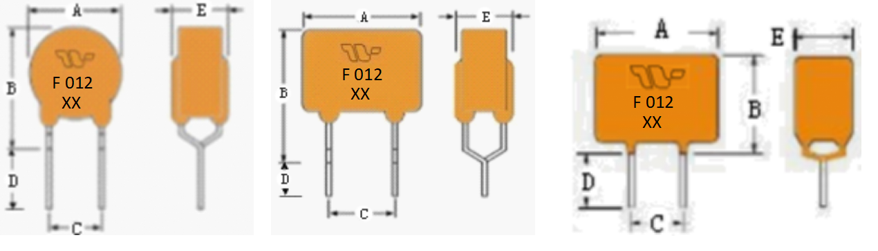
| P/N | A | B | C | D | E | Physical Characteristics | ||
| Max. | Max. | Typ. | Min. | Max. | Style | Lead Φ mm | Material | |
| TRF002 | 7.4 | 12.7 | 5.1 | 7.6 | 4.5 | 1 | 0.5 | CP |
| TRF004 | 5.8 | 9.9 | 5.1 | 7.6 | 4.5 | 1 | 0.5 | CP |
| TRF006 | 5.8 | 9.9 | 5.1 | 7.6 | 4.5 | 1 | 0.6 | Sn/Cu |
| TRF008 | 7.4 | 12.7 | 5.1 | 7.6 | 4.5 | 1 | 0.6 | Sn/Cu |
| TRF009 | 7.4 | 12.7 | 5.1 | 7.6 | 4.5 | 1 | 0.6 | Sn/Cu |
| TRF011 | 6.5 | 11.0 | 5.1 | 5.0 | 4.5 | 2 | 0.6 | Sn/Cu |
| TRF012 | 6.8 | 12.0 | 5.1 | 7.6 | 4.5 | 2 | 0.6 | Sn/Cu |
| TRF012U | 6.8 | 12.0 | 5.1 | 7.6 | 4.5 | 2 | 0.6 | Sn/Cu |
| TRF014 | 6.5 | 11.0 | 5.1 | 5.0 | 4.5 | 2 | 0.6 | Sn/Cu |
| TRF014U | 6.0 | 10.0 | 5.1 | 4.7 | 4.5 | 2 | 0.6 | Sn/Cu |
| TRF018 | 10.2 | 14.5 | 5.1 | 7.6 | 4.5 | 1 | 0.6 | Sn/Cu |
| TRF018U | 10.2 | 14.5 | 5.1 | 7.6 | 4.5 | 1 | 0.6 | Sn/Cu |
| TRF020 | 10.5 | 17.0 | 5.1 | 7.6 | 4.5 | 1 | 0.6 | Sn/Cu |
| TRF030 | 11.0 | 16.8 | 5.1 | 7.6 | 4.5 | 1 | 0.6 | Sn/Cu |
| TRF040 | 11.7 | 17.0 | 5.1 | 7.6 | 3.8 | 1 | 0.6 | Sn/Cu |
| TRF050 | 13.0 | 18.0 | 5.1 | 7.6 | 3.8 | 2 | 0.6 | Sn/Cu |
| TRF060 | 14.0 | 19.5 | 5.1 | 7.6 | 3.8 | 2 | 0.6 | Sn/Cu |
| TRF080 | 16.3 | 21.3 | 5.1 | 7.6 | 3.8 | 3 | 0.8 | Sn/Cu |
| TRF100 | 17.8 | 22.9 | 5.1 | 7.6 | 3.8 | 3 | 0.8 | Sn/Cu |
| TRF200 | 28.4 | 33.5 | 10.2 | 7.6 | 3.8 | 3 | 0.8 | Sn/Cu |
Temperature Rerating
| P/N | Hold Current At Different Ambient Operating Temperature | ||||||||
| -40℃ | -20℃ | 0℃ | 25℃ | 40℃ | 50℃ | 60℃ | 70℃ | 85℃ | |
| TRF002 | 0.031 | 0.028 | 0.023 | 0.020 | 0.017 | 0.015 | 0.013 | 0.011 | 0.008 |
| TRF004 | 0.062 | 0.055 | 0.048 | 0.040 | 0.033 | 0.029 | 0.026 | 0.022 | 0.017 |
| TRF006 | 0.093 | 0.075 | 0.071 | 0.06 | 0.05 | 0.044 | 0.038 | 0.033 | 0.025 |
| TRF008 | 0.124 | 0.110 | 0.095 | 0.080 | 0.066 | 0.059 | 0.051 | 0.044 | 0.033 |
| TRF009 | 0.140 | 0.124 | 0.110 | 0.090 | 0.075 | 0.068 | 0.058 | 0.050 | 0.038 |
| TRF011 | 0.171 | 0.151 | 0.131 | 0.110 | 0.091 | 0.081 | 0.071 | 0.061 | 0.046 |
| TRF012(U) | 0.186 | 0.165 | 0.143 | 0.120 | 0.099 | 0.088 | 0.077 | 0.066 | 0.050 |
| TRF014(U) | 0.225 | 0.199 | 0.172 | 0.145 | 0.119 | 0.106 | 0.093 | 0.080 | 0.060 |
| TRF018(U) | 0.269 | 0.240 | 0.211 | 0.180 | 0.153 | 0.138 | 0.123 | 0.109 | 0.087 |
| TRF020 | 0.310 | 0.275 | 0.237 | 0.200 | 0.165 | 0.147 | 0.128 | 0.110 | 0.082 |
| TRF030 | 0.465 | 0.413 | 0.356 | 0.300 | 0.248 | 0.221 | 0.192 | 0.165 | 0.123 |
| TRF040 | 0.620 | 0.550 | 0.475 | 0.400 | 0.33 | 0.295 | 0.255 | 0.220 | 0.165 |
| TRF050 | 0.775 | 0.688 | 0.594 | 0.500 | 0.412 | 0.366 | 0.319 | 0.275 | 0.206 |
| TRF060 | 0.930 | 0.825 | 0.710 | 0.600 | 0.495 | 0.443 | 0.393 | 0.330 | 0.246 |
| TRF080 | 1.240 | 1.100 | 0.950 | 0.800 | 0.660 | 0.590 | 0.510 | 0.440 | 0.330 |
| TRF100 | 1.55 | 1.38 | 1.19 | 1.00 | 0.83 | 0.74 | 0.64 | 0.55 | 0.41 |
| TRF200 | 3.10 | 2.75 | 2.38 | 2.00 | 1.65 | 1.48 | 1.28 | 1.10 | 0.83 |
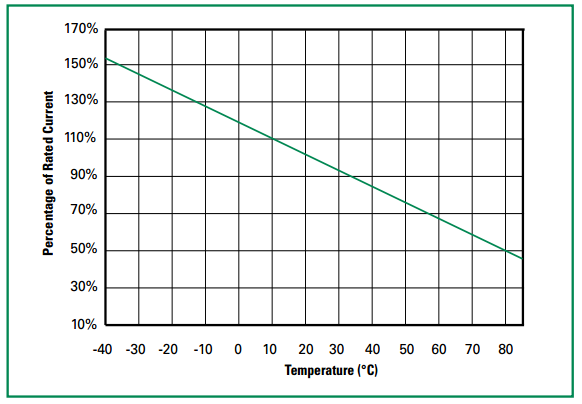
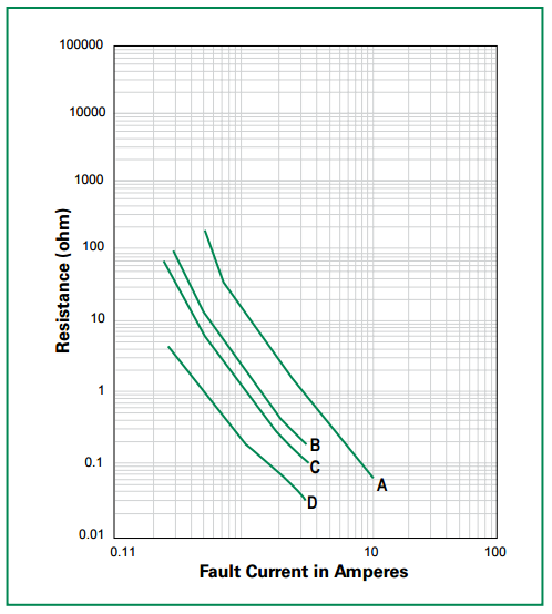
The average time current curves and Temperature Rerating curve performance is affected by a number or variables, and these curves provided as guidance only. Customer must verify the performance in their application.
| Curve Designation | I hold (A) |
| A | 0.18 |
| B | 0.145 |
| C | 0.12 |
| D | 0.80 |
Typical time to trip at 25℃
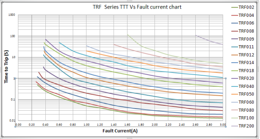
The Time to Trip curves represent typical performance of a device in a simulated application environment. Actual performance in specific customer applications may differ from these values due to the influence of other variables.
Package Info
A: Bulk
| Part Number | Q'ty/Bag |
| TRF002-TRF040 | 1000 pcs |
| TRF050-TRF100 | 500 pcs |
| TRF200 | 200 pcs |
TRF012 : 20000 Pieces Per Carton Box, 6.5kg/Carton Box
B: Tape and Reel Specification
Devices taped using EIA468–B/IEC286-2 standards.
Physical Specifications
| Lead Material | CP or Sn/Cu |
| Soldering Characteristics | Solderability per MIL–STD–202, Method 208 |
| Insulating Material | Cured, flame retardant epoxy polymer meets UL94V-0 requirements. |
Environmental Specifications
| Operating/Storage Temperature | -40°C to +85°C |
| Maximum Device Surface Temperature in Tripped State | 125°C |
| Passive Aging | 65°C/85°C, 1000 hours |
| Humidity Aging | +85°C, 85% R.H,.1000 hours |
| Thermal Shock | MIL–STD–202, Method 107 +125°C to -55°C 10 times |
| Solvent Resistance | MIL–STD–202, Method 215 |
| Moisture Sesitivity Level | Level 1, J–STD–020 |
Agency Specification Selection Guide For Telecom and Networking Applications
| Power | Lightning | Power Cross |
| TRF012 TRF014 | ITU K.20/21/45 – 1.5kV 10/700μs ITU K.20/21/45 – 4kV 10/700μs* | ITU K.20/21/45 – 230Vac, 10Ω ITU K.20/21/45 – 600Vac, 600Ω |
| TRF018 | ITU K.20/21/45 – 1.5kV 10/700μs ITU K.20/21/45 – 4kV 10/700μs* Telcordia GR – 974 – 1.0kV 10/1000μs | ITU K.20/21/45 – 230Vac, 10Ω ITU K.20/21/45 – 600Vac, 600Ω Telcordia GR – 974- 283Vac, 10A |
*Devices should be independently evaluated and tested for use in any specific application
Protection Application Guide
| Region/Specification | Application | Device Selection |
| South America/Asia/Europe ITU K.45 | *Access network equipment Remote terminal Repeaters WAN equipment Cross –connect | TRF018 TRF018U TRF014 TRF014U TRF012 TRF012U |
| South America/Asia/Europe ITU K.21 | Customer and IT equipment Analog modems ADSL, xDSL Phone sets, PBX systems Internet appliances POS terminals | TRF018 TRF018U TRF014 TRF014U TRF012 TRF012U |
| South America/Asia/Europe ITU K.20 | Central Office POTS/ISDN linecards T1/E1/J1 linecards ADSL/VDSL splitters SU/DSU | TRF018 TRF018U TRF014 TRF014U TRF012 TRF012U |
| North America Telcordia GR-974 | *Primary protection modules DF modules Network interface | TRF018 TRF018U TRF014 TRF014U TRF012 TRF012U
|
| South America/Asia/Europe ITU K.20 | ||
| North America Telcordia GR-1089 | *Intrabuilding communication systems LAN, VOIP cards Local loop handsets | TRF018 TRF018U TRF014 TRF014U TRF012 TRF012U
|
| South America/Asia/Europe ITU K.20 and K.21 | ||
| LAN Intrabuilding power cross Protection LAN equipment, IP phone | TRF018 TRF018U TRF014 TRF014U TRF012 TRF012U |
Comparison of technologies
One shot fuses(One-time fuse, normally called SMD Fuse,Glass Fuse,Ceramic Fuse,Subminiature fuse,thermal fuse etc.), which are based on melting of a metal link, must be replaced after a single high current event. They are commonly seen in applications like LED bulbs where a simple device makes sense. For LED bulbs the solution to a blown fuse is just to purchase another bulb. It is a small expense and the fault leading to the open fuse likely requires replacement of the bulb anyway. PTC resettable fuses are a step-up from one shot fuses. When a short circuit occurs, they heat up and transition from a low resistance state to a high resistance state. Allowing them to cool down (typically by removing the power) resets them to the low resistance state.
Resettable PTC fuse come in both ceramic (CPTC) and polymer (PPTC) types. Ceramic types are used in sensitive application spaces such as telecom where the resistance must not change much after tripping. The polymer type is used in many general electronics applications and is sometimes called alternatively a resettable fuse, or polyswitch. , here,a polymer type is compared against an eFuse. eFuses utilize a completely different operating principle than one-shot or PTC fuses. Instead of limiting current based entirely on heating, eFuses actually measure the current and turn off an internal switch if the current exceeds a specified limit.
Also, since eFuses are semiconductor integrated circuit devices they have a rapid (typically less than 10 s) response to short circuits as well as a plethora of features that may be included:
• Ability to operate over temperature with minimal shift in parameters
• No degradation after a fault; the on resistance does not depend on how many faults have occurred
• Programmable current limit
• Enable pin, to turn on or off the device
• Fault pin, to signal that something has gone wrong to control logic or other power rails
• Soft-start, to limit inrush current
•Voltage clamp, to prevent voltage spikes from reaching the load
• Choice of latch-off or auto-retry, so that everything will reset if the load recovers, but without needing to turn off the power
• Reverse current blocking
However, the eFuse arguably also has a few disadvantages such as having more terminals and requiring bias current to operate.
At the most basic level, an eFuse requires at least three terminals due to its architecture. These are input, output, and ground. In some cases it would be better to have a two-terminal device to make layout routing easier. For example, there is no need to connect a PTC to the ground plane.
Also, since the PTC resettable fuse does not require a ground pin, current only flows from input to output. This means that no bias current is required at all. This is an obvious advantage for battery-powered applications. However, the latest eFuses have reduced bias current considerably. For example, when the NIS5452 is turned off, its bias current is less than 100 A. Its predecessor, the NIS5135 has a bias current about 10 times higher. While it is true that the eFuse is more complicated due to its semiconductor architecture, advances in semiconductor technology have significantly reduced the size, and therefore expense, of eFuses. For example, one of the first eFuses from ON Semiconductor is the NIS5112 with 30 m RDS(on) in the SOIC−8 (5 × 4 × 1.75 mm) package. By contrast the upcoming NIS5020 is in a much smaller (3 × 3 × 1.0 mm) DFN10 package and has half the RDS(on).